Installation
Correct installation and maintenance is important for ensuring product performance. Ostberg provides various aids to ensure efficient, hassle-free commissioning and long product service life.
Project Planning advice
Recommended installation
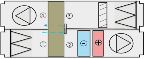
The best flow conditions are achieved when supply and exhaust air fans are installed on the suction side of the regenerative heat recovery unit. A reasonable pressure difference between the supply air and exhaust air ducts p2-3 is obtained in almost all installations. It is possible to install a trim damper in the exhaust air to regulate pressure difference p2-3.
Alternatively, the outside airflow fan can be located in the direction of flow upstream of the rotor. This variation is often found in hospital installations where the entire supply air section is run at overpressure. The risk of supply air contamination is thus eliminated. Furthermore, installations with pusher outside air fans are of interest when maximum cooling recovery is preferred, as the heat generated by the outside air fan is largely transferred to outlet air via the rotor.
Constant pressure and recirculating air
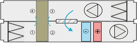
Blow through exhaust air fans and draw through outside air fans are typical in installations with a recirculating air function, or in installations where constant duct pressure is necessary. Furthermore, exhaust air fan heat generation contributes to heat recovery.
The system leads to a negative pressure differential between p2-3 and because a purge sector is unable to function correctly, it should not be installed. Therefore blow through exhaust air fans should only be used in systems where recirculating air is allowed.
Inspection
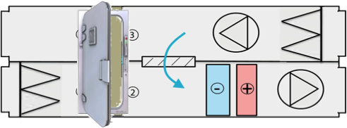
It is important when installing rotors to consider service, maintenance and cleaning. Hatches are necessary on the inspection side to allow access to control equipment, motors, drive belts and brushsealings. It’s preferable to have a service door (on the Air Handling Unit) that gives access to the whole hight of the rotor, this to create best possible space for inspection and maintenance. If the space around the Air Handling Unit is limited a minimum request is to have an Service Triangel placed in the corner where the drive motor is located. Observe that the Service triangel shall be easily acceable inside the Air Handling Unit
Airflow disturbance
Rotor performance calculations are based on undisturbed airflows in and out. Uneven airflow speed profiles have a negative effect on rotor performance, component location should be carefully planned in a ventilation installation.

Distance to components
Generally speaking, air handling components should not be placed too close to the rotor in order to prevent in- and outflow disturbances to the rotor.
Air containing particulates
Experience shows that the rotor can be run with a moderate amount of particulates in the air. Due to the laminar airflow inside the rotormatrix a self-cleaning effect is achieved when the rotor switches airflow directions between outside and exhaust air. If particulates does remain on the outer surface of the rotor these can be vacuum cleaned or washed away. It is always recommended to install an air filter in the direction of airflow upstream of the rotor in order to protect the rotor from contamination. It is advisable to install an exhaust air oil filter in installations with kitchen exhaust air.