Drive equipment
Drive equipment is consist of motor, control unit and belt.Ostberg provides easy, operationally reliable drive equipment for both constant and variable speed operation.
Rotors are driven by a motor mounted on a bracket inside the casing. All rotors are driven by the motor via a belt to the rotor periphery. Rotors Ø<1400 mm are driven by round belts and rotors Ø>1400 are driven by V-belts.
All motors are 4-pole with integrated thermo-switches that monitor winding temperatures. Ostberg provides both three-phase and single-phase motors.
Belt pulley size and/or gearing are dimensioned to achieve optimum rotor rpm. Optimum rotor speed for heat recovery is 12 rpm, and for moisture recovery (sorption rotors) 20 rpm.
1. Constant drive
Constant drive means that rotor speed remains constant during operation, or is switched off to remain stationary – so called on/off drive.Induction motors with reduction gearing are available in three-phase and single-phase versions. These are mainly used in small units and are available with outputs of 6W, 25W and 40W. The motors have class B insulation and IP54 protection ratings. The reduction gear is life-time lubricated and maintenance-free.
Asynchronous motors with worm gears are available in three-phase and single-phase versions. They are available with outputs between 90W and 750W. The motors have class F insulation and IP55 protection ratings. The worm gears are life-time lubricated and maintenance-free.
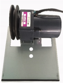
Asynchronous motors with worm gears are available in three-phase and single-phase versions. They are available with outputs between 90W and 750W. The motors have class F insulation and IP55 protection ratings. The worm gears are life-time lubricated and maintenance-free.
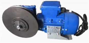
Ostberg Drive Equipment and Technical Specification
| 1-phase 50 Hz | ||||||||
|---|---|---|---|---|---|---|---|---|
| Drive motor | SPG6-1 | SPG25-1 | SPG40-1 | AP56E-1 | AP63E-1 | AP71E-1 | AP80E-1 | |
| Voltage | V | 1x230 | 1x230 | 1x230 | 1x230 | 1x230 | 1x230 | 1x230 |
| Frequency | Hz | 50 | 50 | 50 | 50 | 50 | 50 | 50 |
| Engine power | kW | 0,006 | 0,025 | 0,04 | 0,09 | 0,18 | 0,37 | 0,75 |
| Electricity | A | 0,07 | 0,26 | 0,36 | 0,90 | 1,60 | 3,20 | 5,60 |
| Weight | kg | 1,0 | 1,8 | 3,4 | 4,7 | 6,2 | 10,3 | 15,0 |
| 3-phase 50 Hz | ||||||||
| Drive motor | SPG40-3 | SPG40-3 | AP56-3 | AP63-3 | AP71-3 | AP80-3 | ||
| Voltage | V | 3x230 | 3x400 | 3x220/380 | 3x220/380 | 3x220/380 | 3x220/380 | |
| Frequency | Hz | 50 | 50 | 50 | 50 | 50 | 50 | |
| Engine power | kW | 0,04 | 0,04 | 0,09 | 0,18 | 0,37 | 0,75 | |
| Electricity | A | 0,39 | 0,21 | 0,77/0,45 | 1,23/0,71 | 2,02/1,17 | 3,50/2,03 | |
| Weight | kg | 3,4 | 3,4 | 4,3 | 5,4 | 8,1 | 14 | |
| 3-phase 60 Hz | ||||||||
| Drive motor | SPG40-3 | SPG40-3 | AP56-3-60 | AP63-3-60 | AP71-3-60 | AP80-3-60 | ||
| Voltage | V | 3x230 | 3x400 | 3x264/456 | 3x255/440 | 3x264/456 | 3x264/456 | |
| Frequency | Hz | 60 | 60 | 60 | 60 | 60 | 60 | |
| Engine power | kW | 0,04 | 0,04 | 0,11 | 0,22 | 0,44 | 0,90 | |
| Electricity | A | 0,33 | 0,19 | 0,77/0,45 | 1,23/0,71 | 2,02/1,17 | 3,50/2,03 | |
| Weight | kg | 3,4 | 3,4 | 4,3 | 5,4 | 8,1 | 14 |
2. Variable drive
Variable drive enables rotor speed regulation and thus optimal control throughout the year.
The drive unit consists of a motor and control unit that regulates motor rpm in relation to an input signal.
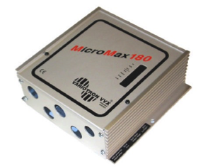
MicroMax
Micromax is a standardized, user-friendly control unit with all necessary functions.
Micromax is controlled by 0-10 V input signals.
Rotor speed is proportional to the control unit input signal. If the input signal drops below a set threshold value, the motor will stop.
Micromax is connected to 4-pole induction motors with reduction gears or 4-pole asynchronous motors with worm gears. All motors are three-phase versions equipped with thermo-switches.
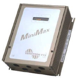
MiniMax
Minimax is a standardized, user-friendly control unit with all necessary functions.Minimax is controlled by all available input signals.Rotor speed is proportional to the control unit input signal. If the input signal drops below a set threshold value, the motor will stop.Minimax is available in one model and can drive rotors < Ø 3500 mm.
VariMax
VariMax is a standardized, user-friendly control unit with all necessary functions.VariMax is controlled by 0-10 V input signals.Rotor speed is proportional to the control unit input signal. If the input signal drops below a set threshold value, the motor will stop.Minimax is available in one model and can drive rotors < Ø 3900 mm.VariMax has a rotation monitor (magnet mounted on the wheel with associated magnet transmitter) and built-in cleaning function. The functions can be disconnected via DIP switches.
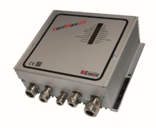
| Control units, summary | |||||
|---|---|---|---|---|---|
| MicroMax | MiniMax | VariMax | |||
| Connection voltage | 1x230V +6-10% | 1x230V +6-10% | 1x230V +-15% | ||
| Connection frequency | 50-60Hz | 50-60Hz | 50-60Hz | ||
| Motor type | Asynchronous | Asynchronous | Asynchronous | ||
| safety class | IP 54 | IP 54 | IP 54 | ||
| ambient temperature | -20 - +45°C | -20 - +45°C | -30 - +45°C | ||
| Direction of rotation | Fixed | Fixed | Fixed | ||
| input signals (control signals) | 0-10V | 0-5V, 0-10V, 0-20V | 0-10V | ||
| 0-20mA 4-20mA” | 0-20mA 4-20mA” | ||||
| lowest constant rpm | 4 Hz | 4 Hz | -- | ||
| rotation guard | Magnetic sensor | Magnetic sensor | Magnetic sensor | ||
| Purge function | 10s (every 30 min) | 10s (every 30 min) | 20s (every 30 min) | ||
| Defrost function | Integrated function | Integrated function | Integrated function | ||
| symbol | Operational status | Operational status | Operational status | ||
| Alarm | Alarm | Alarm | |||
| Max rotor diameter | Ø≤5000 | Ø≤3500 | Ø≤3900 | ||
| Built-in display | No | No | No | ||